ACZCH4H4R09
From Technical Support Wiki
ACZCI4H4R09 is the 15 SEER 9,000 Btu outdoor unit of the Blue Series.
Wiring Diagram
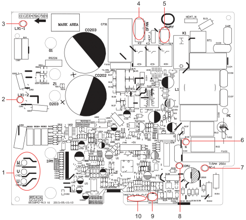
PCB Printed Diagram
| Number | Description |
|---|---|
| 1 | Compressor UVW three phases |
| 2 | Reactor interface 2 |
| 3 | Reactor interface 1 |
| 4 | Fan interface |
| 5 | 4-way valve interface |
| 6 | Power supply neutral wire |
| 7 | Power supply neutral wire |
| 8 | Communication wire |
| 9 | Overload input |
| 10 | Temperature sensor interface |
Exploded View and Parts List
| Number | Part Name |
|---|---|
| 1 | Front Grill |
| 2 | Cabinet |
| 3 | Chassis Sub-Assy |
| 4 | Compressor Gasket |
| 5 | Electrical Heater (Compressor) |
| 6 | Compressor and Fittings |
| 7 | Valve Support |
| 8 | Valve |
| 9 | Valve |
| 10 | Valve Cover |
| 11 | Cable Cross Plate 1 |
| 12 | Cable Cross Plate 2 |
| 13 | Right Side Plate |
| 14 | Cover of Pass Wire |
| 15 | 4-Way Valve Assy |
| 16 | Magnet Coil |
| 17 | Temp Sensor Sleeving |
| 18 | Electric Expansion Valve Sub-Assy |
| 19 | Magnet Coil |
| 20 | Rear Grill |
| 21 | Condenser Assy |
| 22 | Compressor Overload Protector (External) |
| 23 | Clapboard Sub-Assy |
| 24 | Top Cover Plate |
| 25 | Cover of Reactor Box |
| 26 | Reactor |
| 27 | Reactor |
| 28 | Motor Support Spot Welding Sub-Assy |
| 29 | Fan Motor |
| 30 | Axial Flow Fan |
| 31 | Electric Box Cover Sub-Assy |
| 32 | Magnetic Ring |
| 33 | Main Board |
| 34 | Radiator |
| 35 | Electric Box 1 |
| 36 | Terminal Board |
| 37 | Wire Clamp |
| 38 | Electric Box Assy |
| 39 | Temperature Sensor |
Piping Sizes
| Liquid Side | Gas Side |
|---|---|
| 1/4" | 3/8" |


