A13CH4H4G09
From Technical Support Wiki
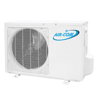
A13CH4H4G09 is the 13 SEER 9,000 Btu mini split in the Bronze Series line.
Power and Signal Cable Wiring Diagram
Note: As per the technical specifications the voltage for A13CH4H4G09 is 115V.
Please click here for a PDF of the power and signal cable wiring diagram.
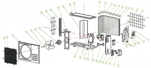
Exploded View and Parts List
| Number | Part Name |
|---|---|
| 1 | Front Grill |
| 2 | Grill Clip |
| 3 | Front Plate |
| 4 | Nut |
| 5 | Gasket |
| 6 | Axial Flow Fan |
| 7 | Motor |
| 8 | Motor Support |
| 9 | Left Protect Net |
| 10 | Pillar |
| 11 | PE Sponge |
| 12 | Partition Board |
| 13 | Small Handle |
| 14 | Top Panel |
| 15 | Electric Box |
| 16 | Compressor Capacitor |
| 17 | PU Sponge |
| 18 | Condenser |
| 19 | Capacitor Clamp |
| 20 | Fan Capacitor |
| 21 | Terminal Board |
| 22 | Wire Clip |
| 23 | 4-Way Valve Assembly |
| 24 | Intake Pipe for the Condenser |
| 25 | Rear Grill |
| 26 | Damping Rubber for Capillary |
| 27 | Capillary Assembly |
| 28 | Drainpipe for the Condenser |
| 29 | Discharge Pipe |
| 30 | Damping Rubber |
| 31 | Suction Pipe |
| 32 | Valve Cover |
| 33 | High-Pressure Valve |
| 34 | Low-Pressure Valve |
| 35 | Valve Installation Plate |
| 36 | Large Handle |
| 37 | Right Panel |
| 38 | Power Cord |
| 39 | Anti-Vibration Pad for the Compressor |
| 40 | Compressor |
| 41 | Gasket |
| 42 | Nut |
| 43 | Base |
Piping Sizes
| Liquid Side | Gas Side |
|---|---|
| 1/4" | 1/2" |
Error Codes
| Code | Error Name | Description/Troubleshooting |
|---|---|---|
| DF | Defrost | Currently in defrost mode. Will return to normal operations when defrost is finished. |
| E2 | Room Temp Sensor Fault |
Accessories |

