A13EM4H4G12
From Technical Support Wiki
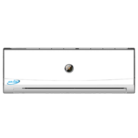
A13CH4H4G12 is the 13 SEER 12,000 Btu mini split in the Bronze Series line.
Remote Control
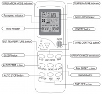
| Button Name | Description |
|---|---|
| OPERATION MODE Indicator | Indicates selected operation mode. |
| FAN SPEED Indicator | Indicates the selected Air Rate. |
| TIME Indicator | During TIMER operation indicates the timer. During normal operation, it indicates the time. |
| SET TEMPERATURE | This button sets the room temperature. |
| SLEEP | This button changes to SLEEP operation. |
| AUTOSTART | This button is used for timing the AUTOSTART function. |
| AUTOSTOP | This button is used for timing the AUTOSTOP function |
| TEMPERATURE Indicator | Indicates the set temperature. |
| AIR FLOW Indicator | Indicates the selected flap mode. |
| ON/OFF | Controls the powered state of the mini split. |
| VANE CONTROL | This button changes the flap mode. |
| MODE | This button, whenever pressed, changes the operation mode in the following order: Auto->Cool->Dry->Heat->Fan. |
| FAN SPEED | This button sets the air rate. |
| SWING | This button adjusts the air swinging direction. |
| TIME SET | These two buttons are used for setting the time as well as autostart and stop times. |
Exploded View and Parts List
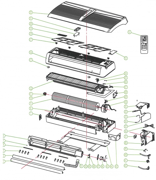
| Number | Part Name |
|---|---|
| 1 | Down Louver |
| 2 | Up Louver |
| 3 | Swing Louver |
| 4 | Swing Louver Connecting Lever |
| 5 | Guide Louver Bearing |
| 6 | Outlet Part |
| 7 | Left Angle Plate |
| 8 | Base |
| 9 | Cross Flow Fan |
| 10 | Cross Flow Fan Bearing |
| 11 | Ring of Cross Flow Fan Bearing |
| 12 | Evaporator assembly |
| 13 | |
| 14 | |
| 15 | Screw Cover |
| 16 | Middle Frame |
| 17 | Front Clip |
| 18 | Air Filter |
| 19 | Cold Catalyst |
| 20 | Display Box Cover |
| 21 | Display Box |
| 22 | Front Panel |
| 23 | Middle Frame Coverplate |
| 24 | Room Temp. Sensor Holder |
| 25 | Insert Block |
| 26 | Copper Pipe of Sensor |
| 27 | Pipe Clamp |
| 28 | Evaporator Right Fixed Plate |
| 29 | Motor Plate |
| 30 | Motor |
| 31 | Electric Box Cover |
| 32 | Display Lamp Panel |
| 33 | Tube Temp. Sensor |
| 34 | Room Temp. Sensor |
| 35 | Electric Control Plate |
| 36 | Connecting Wire |
| 37 | Transformer |
| 38 | Electric Box |
| 39 | Wire Clip |
| 40 | Connecting Cable |
| 41 | Terminal Board |
| 42 | Power Cord |
| 43 | Right Angle Plate |
| 44 | Wall-Mounting Frame |
| 45 | Screw |
| 46 | Step Motor |
| 47 | Motor Fixed Plate |
| 48 | Crank Connecting Rod |
| 49 | Upper Crank |
| 50 | Lower Crank |
| 51 | Thermal Insulation Pipe |
| 52 | Remote Controller |


