AMSCI4H4S18 is the 18,000 Btu outdoor unit of Multi Plus Series.
Multi Plus condenser (18k)
Wiring Diagram

AMSCI4H4S18 Wiring Diagram
Exploded View and Parts List
| Number
|
Part Description
|
| 1
|
Fan Guard
|
| 2
|
Front Panel
|
| 3
|
Left Guard Filter
|
| 4
|
Mounting Plate
|
| 5
|
Welding Hex Nuts
|
| 6
|
Propeller Fan
|
| 7
|
Fan Motor
|
| 8
|
Motor Bracket
|
| 9
|
Upper Cover
|
| 10
|
Back Guard Filter
|
| 11
|
Side Panel Parts
|
| 12
|
PFC Inductance
|
| 13
|
Separate Plate Assy
|
| 14
|
Valve Cover
|
| 15
|
Sensor Mounting Plate
|
| 16
|
Handle
|
| 17
|
Baffle
|
| 18
|
Fixed Board
|
| 19
|
Tube Electric Heater
|
| 20
|
Condenser Assy
|
| 21
|
Pipe Assy
|
| 22
|
Outlet Tube Assy
|
| 23
|
Electric Expansion Valve Assy
|
| 24
|
Electromagnetic Coil A
|
| 25
|
Electromagnetic Coil B
|
| 26
|
Electromagnetic Coil C
|
| 27
|
1/4 Stop Valve Assy
|
| 28
|
3/8 Stop Valve Assy
|
| 29
|
Base Parts
|
| 30
|
Mounting Plate
|
| 31
|
Compressor
|
| 32
|
Noise Insulation Cotton
|
| 33
|
Noise Insulation Cotton
|
| 34
|
Electric Heating Belt
|
| 35
|
Noise Insulation Cotton
|
| 36
|
Noise Insulation Cotton
|
| 37
|
Suction Tube Assy
|
| 38
|
Discharge Tube Assy
|
| 39
|
4-Way Valve Assy
|
| 40
|
Mounting Plate
|
| 41
|
Driver Board
|
| 42
|
Outdoor Main Control Board
|
| 43
|
Filter Board
|
| 44
|
Electric Joint Box Assy
|
| 45
|
Capacitor
|
| 46
|
Radiator
|
| 47
|
Connect Terminal Panel
|
| 48
|
Power Terminal Panel
|
| 49
|
Clamp
|
| 50
|
Clamp
|
| 51
|
Temperature Sensor
|
| 52
|
Temperature Sensor
|
| 53
|
Temperature Sensor
|
| 54
|
4-Way Valve
|
PCB Printed Diagram
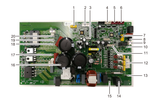
AMSCI4H418 PCB Printed Diagram Main Board
| Number
|
Description
|
| 1
|
Driver EE Data Socket
|
| 2
|
DC Motor
|
| 3
|
For Developer
|
| 4
|
Electronic Expansion Valve B
|
| 5
|
Electronic Expansion Valve A
|
| 6
|
For Developer
|
| 7
|
Main EE Data Socket
|
| 8
|
4-Way Valve
|
| 9
|
Electric Heating Belt
|
| 10
|
Base Heater
|
| 11
|
Sensor Signal from Sensor Board
|
| 12
|
Communication Signal to Indoor Unit
|
| 13
|
AC Power Lin
|
| 14
|
AC Power Nin
|
| 15
|
Ground
|
| 16
|
Reactor L1
|
| 17
|
Reactor L2
|
| 18
|
Compressor U
|
| 19
|
Compressor V
|
| 20
|
Compressor W
|

AMSCI4H418 PCB Printed Diagram Sensor & Maintenance Board
| Number
|
Description
|
| 1
|
Driver EE Data Socket
|
| 2
|
DC Motor
|
| 3
|
For Developer
|
| 4
|
Electronic Expansion Valve B
|
| 5
|
Electronic Expansion Valve A
|
| 6
|
For Developer
|
| 7
|
Main EE Data Socket
|
| 8
|
4-Way Valve
|
| 9
|
Electric Heating Belt
|
| 10
|
Base Heater
|
| 11
|
Sensor Signal from Sensor Board
|
| 12
|
Communication Signal to Indoor Unit
|
| 13
|
AC Power Lin
|
| 14
|
AC Power Nin
|
| 15
|
Ground
|
| 16
|
Reactor L1
|
| 17
|
Reactor L2
|
| 18
|
Compressor U
|
| 19
|
Compressor V
|
| 20
|
Compressor W
|


