ABXCI4H4S24
From Technical Support Wiki
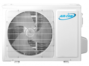
ABXCI4H4S24 is the 21 SEER 24,000 Btu outdoor unit of Blue Series 3.
Wiring Diagram
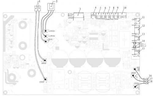
PCB Printed Diagram
| Number | Description |
|---|---|
| 1 | Terminal of Reactor |
| 2 | Terminal of Compressor (White) |
| 3 | Terminal of DC Fan (White) |
| 4 | Heat Sink Temperature Sensor (White) |
| 5 | Pressure Protector (Black) |
| 6 | Compressor Discharge Temperature Sensor (Yellow) |
| 7 | Outdoor Ambient Temperature Sensor (White) |
| 8 | Outdoor Pipe Temperature Sensor (Red) |
| 9 | Terminal of Compressor Overload Protector (White) |
| 10 | Terminal of Electronic Expansion Valve (White) |
| 11 | DRED Function |
| 12 | Terminal of AC Fan (White) |
| 13 | Cool Valve Terminal |
| 14 | Heater Terminal |
| 15 | 4-way Valve Terminal (Black) |
| 16 | Terminal of Signal Wire to Terminal Block |
| 17 | Terminal of Live Wire to Terminal Block |
| 18 | Terminal of Neutral Wire to Terminal Block |
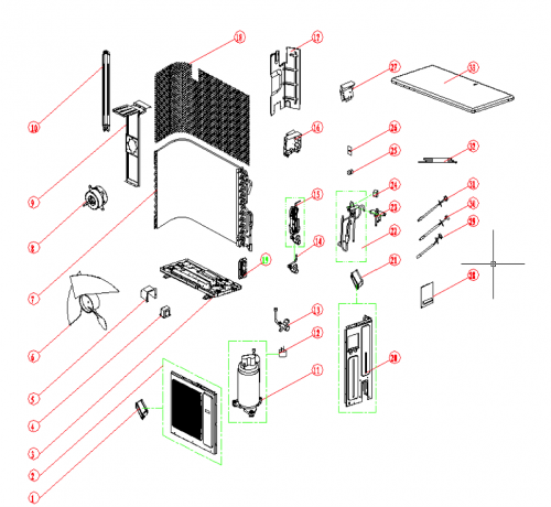
Exploded View and Parts List
| Number | Part Name |
|---|---|
| 1 | Handle |
| 2 | Panel Parts |
| 3 | Base Holder Part |
| 4 | PFC Inductance |
| 6 | Propeller Fan Blade |
| 7 | Condenser Assembly |
| 8 | Fan Motor |
| 9 | Motor Supporter |
| 10 | Mounting Plate |
| 11 | Compressor |
| 12 | Compressor Overload Protector |
| 13 | 5/8" 3-Way Valve |
| 14 | 3/8" 2-Way Valve |
| 15 | Electronic Expansion Valve Assembly |
| 16 | Controller Component |
| 17 | Clapboard Part |
| 18 | Back Guard |
| 19 | Valve Seat |
| 20 | Right Side Board Part |
| 21 | Handle |
| 22 | 4-Way Reversing Valve Assembly |
| 23 | 4-Way Valve |
| 24 | 4-Way Valve Coil |
| 25 | Wire Terminal Board |
| 27 | Electric Box |
| 28 | Wiring Distribution Cover |
| 29 | Temperature Sensor |
| 30 | Temperature Sensor |
| 31 | Temperature Sensor |
| 32 | Strong Electricity Connect Wire |
| 33 | Top Plate Part |
Piping Sizes
| Liquid Side | Gas Side |
|---|---|
| 3/8" | 5/8" |


