Difference between revisions of "A18CI4H4R24"
From Technical Support Wiki
| Line 2: | Line 2: | ||
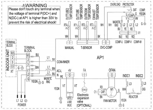
== Wiring Diagram == | == Wiring Diagram == | ||
[[File:Platinum-24k-ODU-WD.png|none|thumb|500px|A18CI4H4R24 Wiring Diagram]] | [[File:Platinum-24k-ODU-WD.png|none|thumb|500px|A18CI4H4R24 Wiring Diagram]] | ||
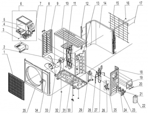
| + | == Exploded View and Parts List == | ||
| + | [[File:Platinum-24k-ODU-EV.jpg|thumb|500px|A18CI4H4R24 Exploded View]] | ||
| + | {| class="wikitable" | ||
| + | ! Number | ||
| + | ! Part Name | ||
| + | |- | ||
| + | | 1 | ||
| + | | Front Grill | ||
| + | |- | ||
| + | | 2 | ||
| + | | Fan Motor | ||
| + | |- | ||
| + | | 3 | ||
| + | | Capacitor | ||
| + | |- | ||
| + | | 4 | ||
| + | | Radiator | ||
| + | |- | ||
| + | | 5 | ||
| + | | Main Board | ||
| + | |- | ||
| + | | 6 | ||
| + | | Electric Box Assy | ||
| + | |- | ||
| + | | 7 | ||
| + | | Terminal Board | ||
| + | |- | ||
| + | | 8 | ||
| + | | Left Handle | ||
| + | |- | ||
| + | | 9 | ||
| + | | Left Side Plate | ||
| + | |- | ||
| + | | 10 | ||
| + | | Coping | ||
| + | |- | ||
| + | | 11 | ||
| + | | Motor Support Sub-Assy | ||
| + | |- | ||
| + | | 12 | ||
| + | | Condenser Support Plate | ||
| + | |- | ||
| + | | 13 | ||
| + | | Clapboard Assy | ||
| + | |- | ||
| + | | 14 | ||
| + | | Condenser Assy | ||
| + | |- | ||
| + | | 15 | ||
| + | | Rear Grill | ||
| + | |- | ||
| + | | 16 | ||
| + | | Wiring Clamp | ||
| + | |- | ||
| + | | 17 | ||
| + | | Temperature Sensor | ||
| + | |- | ||
| + | | 18 | ||
| + | | Right Side Plate | ||
| + | |- | ||
| + | | 19 | ||
| + | | Handle Assy | ||
| + | |- | ||
| + | | 20 | ||
| + | | Retaining Plate | ||
| + | |- | ||
| + | | 21 | ||
| + | | Cut Off Valve | ||
| + | |- | ||
| + | | 22 | ||
| + | | Valve Cover | ||
| + | |- | ||
| + | | 23 | ||
| + | | Valve Support Sub-Assy | ||
| + | |- | ||
| + | | 24 | ||
| + | | Baffle (Valve Support) | ||
| + | |- | ||
| + | | 25 | ||
| + | | Cut Off Valve Sub-Assy | ||
| + | |- | ||
| + | | 26 | ||
| + | | Electric Expand Valve Fitting | ||
| + | |- | ||
| + | | 27 | ||
| + | | 4-Way Valve Assy | ||
| + | |- | ||
| + | | 28 | ||
| + | | Magnet Coil | ||
| + | |- | ||
| + | | 29 | ||
| + | | Compressor and Fittings | ||
| + | |- | ||
| + | | 30 | ||
| + | | Drainage Connector | ||
| + | |- | ||
| + | | 31 | ||
| + | | Chassis Sub-Assy | ||
| + | |- | ||
| + | | 32 | ||
| + | | Drainage Hole Cap | ||
| + | |- | ||
| + | | 33 | ||
| + | | Axial Flow Fan | ||
| + | |- | ||
| + | | 34 | ||
| + | | Front Side Plate Sub-Assy | ||
| + | |- | ||
| + | | 35 | ||
| + | | Cabinet | ||
| + | |} | ||
== Accessories == | == Accessories == | ||
*[[Wall Bracket (QBR-19.5)]] | *[[Wall Bracket (QBR-19.5)]] | ||
*[[Universal Remote (QTH-4000)]] | *[[Universal Remote (QTH-4000)]] | ||
Revision as of 13:49, 11 December 2013
A18CI4H4R24 is the 18 SEER 24,000 Btu outdoor unit of the Platinum Series.
Wiring Diagram
Exploded View and Parts List
| Number | Part Name |
|---|---|
| 1 | Front Grill |
| 2 | Fan Motor |
| 3 | Capacitor |
| 4 | Radiator |
| 5 | Main Board |
| 6 | Electric Box Assy |
| 7 | Terminal Board |
| 8 | Left Handle |
| 9 | Left Side Plate |
| 10 | Coping |
| 11 | Motor Support Sub-Assy |
| 12 | Condenser Support Plate |
| 13 | Clapboard Assy |
| 14 | Condenser Assy |
| 15 | Rear Grill |
| 16 | Wiring Clamp |
| 17 | Temperature Sensor |
| 18 | Right Side Plate |
| 19 | Handle Assy |
| 20 | Retaining Plate |
| 21 | Cut Off Valve |
| 22 | Valve Cover |
| 23 | Valve Support Sub-Assy |
| 24 | Baffle (Valve Support) |
| 25 | Cut Off Valve Sub-Assy |
| 26 | Electric Expand Valve Fitting |
| 27 | 4-Way Valve Assy |
| 28 | Magnet Coil |
| 29 | Compressor and Fittings |
| 30 | Drainage Connector |
| 31 | Chassis Sub-Assy |
| 32 | Drainage Hole Cap |
| 33 | Axial Flow Fan |
| 34 | Front Side Plate Sub-Assy |
| 35 | Cabinet |


