Difference between revisions of "ABSCI4H4S24"
From Technical Support Wiki
(Created page with "ABSCI4H4S24 is the 21 SEER 24,000 Btu outdoor unit of ''Blue Series 2''. right|thumb|''Blue Series 2'' condenser (24k) == Wiring Diagram == File...") |
|||
| Line 4: | Line 4: | ||
== PCB Printed Diagram == | == PCB Printed Diagram == | ||
| − | [[File:Bs2- | + | [[File:Bs2-24-30k-ODU-PCB.png|right|thumb|500px|ABSCI4H4S24 PCB Diagram]] |
{| class="wikitable" | {| class="wikitable" | ||
! Number | ! Number | ||
| Line 10: | Line 10: | ||
|- | |- | ||
| 1 | | 1 | ||
| − | | Terminal of | + | | Terminal of Reactor |
|- | |- | ||
| 2 | | 2 | ||
| − | | Terminal of | + | | Terminal of Compressor |
|- | |- | ||
| 3 | | 3 | ||
| − | | Terminal of | + | | Terminal of DC Fan |
|- | |- | ||
| 4 | | 4 | ||
| − | | | + | | Heat Sink Temperature Sensor |
|- | |- | ||
| 5 | | 5 | ||
| − | | | + | | Pressure Protector |
|- | |- | ||
| 6 | | 6 | ||
| − | | | + | | Compressor Discharge Temperature Sensor |
|- | |- | ||
| 7 | | 7 | ||
| − | | | + | | Outdoor Ambient Temperature Sensor |
|- | |- | ||
| 8 | | 8 | ||
| − | | | + | | Outdoor Pipe Temperature Sensor |
|- | |- | ||
| 9 | | 9 | ||
| − | | | + | | Terminal of Compressor Overload Protector |
|- | |- | ||
| 10 | | 10 | ||
| Line 40: | Line 40: | ||
|- | |- | ||
| 11 | | 11 | ||
| − | | | + | | DRED Function |
|- | |- | ||
| 12 | | 12 | ||
| − | | | + | | Terminal of AC Fan |
|- | |- | ||
| 13 | | 13 | ||
| − | | | + | | Cool Valve Terminal |
|- | |- | ||
| 14 | | 14 | ||
| − | | Terminal | + | | Heater Terminal |
|- | |- | ||
| 15 | | 15 | ||
| − | | | + | | 4-way Valve Terminal |
|- | |- | ||
| 16 | | 16 | ||
| − | | Terminal of | + | | Terminal of Communication Wire to Terminal Block |
| + | |- | ||
| + | | 17 | ||
| + | | Terminal of Signal Wire to Terminal Block | ||
| + | |- | ||
| + | | 18 | ||
| + | | Terminal of Neutral Wire to Terminal Block | ||
|} | |} | ||
<br /> | <br /> | ||
Revision as of 16:36, 7 April 2017
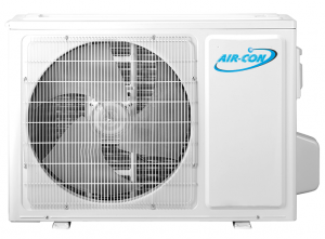
ABSCI4H4S24 is the 21 SEER 24,000 Btu outdoor unit of Blue Series 2.
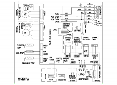
Wiring Diagram
PCB Printed Diagram
File:Bs2-24-30k-ODU-PCB.png
ABSCI4H4S24 PCB Diagram
| Number | Description |
|---|---|
| 1 | Terminal of Reactor |
| 2 | Terminal of Compressor |
| 3 | Terminal of DC Fan |
| 4 | Heat Sink Temperature Sensor |
| 5 | Pressure Protector |
| 6 | Compressor Discharge Temperature Sensor |
| 7 | Outdoor Ambient Temperature Sensor |
| 8 | Outdoor Pipe Temperature Sensor |
| 9 | Terminal of Compressor Overload Protector |
| 10 | Terminal of Electronic Expansion Valve |
| 11 | DRED Function |
| 12 | Terminal of AC Fan |
| 13 | Cool Valve Terminal |
| 14 | Heater Terminal |
| 15 | 4-way Valve Terminal |
| 16 | Terminal of Communication Wire to Terminal Block |
| 17 | Terminal of Signal Wire to Terminal Block |
| 18 | Terminal of Neutral Wire to Terminal Block |
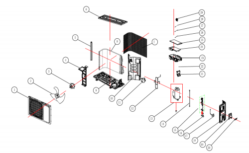
Exploded View and Parts List
| Number | Part Name |
|---|---|
| 1 | Panel Parts |
| 2 | Propeller Fan Blade |
| 3 | Fan Motor |
| 4 | Motor Supporter Assy |
| 5 | Mounting Plate |
| 6 | Upper Board |
| 7 | Back Guard |
| 8 | Condenser Assembly |
| 9 | Base Holder Part |
| 10 | Clapboard |
| 11 | PFC Inductance |
| 12 | Compressor Tube Assembly (cooling Only Models) |
| 13 | Compressor |
| 14 | Compressor Connect Wire |
| 15 | Capillary Assembly |
| 16 | 2-way Valve |
| 17 | 3-Way Valve |
| 18 | Right Side Board |
| 19 | Wiring Distribution Cover Assy |
| 20 | Fixed Board |
| 21 | Connecting Board |
| 22 | Wired Terminal Board |
| 23 | Electric Box |
| 24 | Main Controlling Board Component |
| 25 | Electric Box Cover |
| 26 | Discharge Temperature Sensor |
| 27 | Temperature Sensor |
| 28 | Ambient Temperature Sensor |
| 29 | Sensor Mounting Plate |
Piping Sizes
| Liquid Side | Gas Side |
|---|---|
| 1/4" | 1/2" |


