Difference between revisions of "A13EM4H4G09"
From Technical Support Wiki
| Line 1: | Line 1: | ||
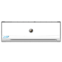
A13CH4H4G09 is the 13 SEER 9,000 Btu mini split in the ''[[Bronze Series]]'' line. [[File:Bronze-evaporator.png|right|thumb|''Bronze Series'' evaporator (9k)]] | A13CH4H4G09 is the 13 SEER 9,000 Btu mini split in the ''[[Bronze Series]]'' line. [[File:Bronze-evaporator.png|right|thumb|''Bronze Series'' evaporator (9k)]] | ||
== Remote Control == | == Remote Control == | ||
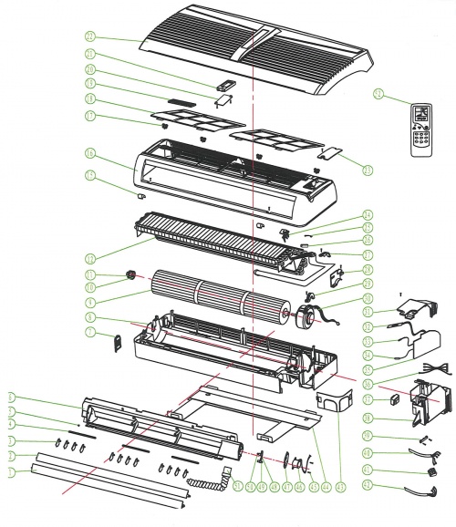
| + | == Exploded View and Parts List == | ||
| + | [[File:Bronze-9k-12k-IDU-EV.jpg|thumb|500px|A13EM4H4G09 Exploded View]] | ||
| + | {| class="wikitable" | ||
| + | ! Number | ||
| + | ! Part Name | ||
| + | |- | ||
| + | | 1 | ||
| + | | Down Louver | ||
| + | |- | ||
| + | | 2 | ||
| + | | Up Louver | ||
| + | |- | ||
| + | | 3 | ||
| + | | Swing Louver | ||
| + | |- | ||
| + | | 4 | ||
| + | | Swing Louver Connecting Lever | ||
| + | |- | ||
| + | | 5 | ||
| + | | Guide Louver Bearing | ||
| + | |- | ||
| + | | 6 | ||
| + | | Outlet Part | ||
| + | |- | ||
| + | | 7 | ||
| + | | Left Angle Plate | ||
| + | |- | ||
| + | | 8 | ||
| + | | Base | ||
| + | |- | ||
| + | | 9 | ||
| + | | Cross Flow Fan | ||
| + | |- | ||
| + | | 10 | ||
| + | | Cross Flow Fan Bearing | ||
| + | |- | ||
| + | | 11 | ||
| + | | Ring of Cross Flow Fan Bearing | ||
| + | |- | ||
| + | | 12 | ||
| + | | Evaporator assembly | ||
| + | |- | ||
| + | | 13 | ||
| + | | | ||
| + | |- | ||
| + | | 14 | ||
| + | | | ||
| + | |- | ||
| + | | 15 | ||
| + | | Screw Cover | ||
| + | |- | ||
| + | | 16 | ||
| + | | Middle Frame | ||
| + | |- | ||
| + | | 17 | ||
| + | | Front Clip | ||
| + | |- | ||
| + | | 18 | ||
| + | | Air Filter | ||
| + | |- | ||
| + | | 19 | ||
| + | | Cold Catalyst | ||
| + | |- | ||
| + | | 20 | ||
| + | | Display Box Cover | ||
| + | |- | ||
| + | | 21 | ||
| + | | Display Box | ||
| + | |- | ||
| + | | 22 | ||
| + | | Front Panel | ||
| + | |- | ||
| + | | 23 | ||
| + | | Middle Frame Coverplate | ||
| + | |- | ||
| + | | 24 | ||
| + | | Room Temp. Sensor Holder | ||
| + | |- | ||
| + | | 25 | ||
| + | | Insert Block | ||
| + | |- | ||
| + | | 26 | ||
| + | | Copper Pipe of Sensor | ||
| + | |- | ||
| + | | 27 | ||
| + | | Pipe Clamp | ||
| + | |- | ||
| + | | 28 | ||
| + | | Evaporator Right Fixed Plate | ||
| + | |- | ||
| + | | 29 | ||
| + | | Motor Plate | ||
| + | |- | ||
| + | | 30 | ||
| + | | Motor | ||
| + | |- | ||
| + | | 31 | ||
| + | | Electric Box Cover | ||
| + | |- | ||
| + | | 32 | ||
| + | | Display Lamp Panel | ||
| + | |- | ||
| + | | 33 | ||
| + | | Tube Temp. Sensor | ||
| + | |- | ||
| + | | 34 | ||
| + | | Room Temp. Sensor | ||
| + | |- | ||
| + | | 35 | ||
| + | | Electric Control Plate | ||
| + | |- | ||
| + | | 36 | ||
| + | | Connecting Wire | ||
| + | |- | ||
| + | | 37 | ||
| + | | Transformer | ||
| + | |- | ||
| + | | 38 | ||
| + | | Electric Box | ||
| + | |- | ||
| + | | 39 | ||
| + | | Wire Clip | ||
| + | |- | ||
| + | | 40 | ||
| + | | Connecting Cable | ||
| + | |- | ||
| + | | 41 | ||
| + | | Terminal Board | ||
| + | |- | ||
| + | | 42 | ||
| + | | Power Cord | ||
| + | |- | ||
| + | | 43 | ||
| + | | Right Angle Plate | ||
| + | |- | ||
| + | | 44 | ||
| + | | Wall-Mounting Frame | ||
| + | |- | ||
| + | | 45 | ||
| + | | Screw | ||
| + | |- | ||
| + | | 46 | ||
| + | | Step Motor | ||
| + | |- | ||
| + | | 47 | ||
| + | | Motor Fixed Plate | ||
| + | |- | ||
| + | | 48 | ||
| + | | Crank Connecting Rod | ||
| + | |- | ||
| + | | 49 | ||
| + | | Upper Crank | ||
| + | |- | ||
| + | | 50 | ||
| + | | Lower Crank | ||
| + | |- | ||
| + | | 51 | ||
| + | | Thermal Insulation Pipe | ||
| + | |- | ||
| + | | 52 | ||
| + | | Remote Controller | ||
| + | |} | ||
== Board == | == Board == | ||
Revision as of 14:37, 17 December 2013
A13CH4H4G09 is the 13 SEER 9,000 Btu mini split in the Bronze Series line.
Remote Control
Exploded View and Parts List
| Number | Part Name |
|---|---|
| 1 | Down Louver |
| 2 | Up Louver |
| 3 | Swing Louver |
| 4 | Swing Louver Connecting Lever |
| 5 | Guide Louver Bearing |
| 6 | Outlet Part |
| 7 | Left Angle Plate |
| 8 | Base |
| 9 | Cross Flow Fan |
| 10 | Cross Flow Fan Bearing |
| 11 | Ring of Cross Flow Fan Bearing |
| 12 | Evaporator assembly |
| 13 | |
| 14 | |
| 15 | Screw Cover |
| 16 | Middle Frame |
| 17 | Front Clip |
| 18 | Air Filter |
| 19 | Cold Catalyst |
| 20 | Display Box Cover |
| 21 | Display Box |
| 22 | Front Panel |
| 23 | Middle Frame Coverplate |
| 24 | Room Temp. Sensor Holder |
| 25 | Insert Block |
| 26 | Copper Pipe of Sensor |
| 27 | Pipe Clamp |
| 28 | Evaporator Right Fixed Plate |
| 29 | Motor Plate |
| 30 | Motor |
| 31 | Electric Box Cover |
| 32 | Display Lamp Panel |
| 33 | Tube Temp. Sensor |
| 34 | Room Temp. Sensor |
| 35 | Electric Control Plate |
| 36 | Connecting Wire |
| 37 | Transformer |
| 38 | Electric Box |
| 39 | Wire Clip |
| 40 | Connecting Cable |
| 41 | Terminal Board |
| 42 | Power Cord |
| 43 | Right Angle Plate |
| 44 | Wall-Mounting Frame |
| 45 | Screw |
| 46 | Step Motor |
| 47 | Motor Fixed Plate |
| 48 | Crank Connecting Rod |
| 49 | Upper Crank |
| 50 | Lower Crank |
| 51 | Thermal Insulation Pipe |
| 52 | Remote Controller |

