Difference between revisions of "ABSCI4H4S12"
From Technical Support Wiki
| (4 intermediate revisions by the same user not shown) | |||
| Line 4: | Line 4: | ||
== PCB Printed Diagram == | == PCB Printed Diagram == | ||
| − | [[File:Bs2- | + | [[File:Bs2-12-18k-ser-18-24k-ODU-PCB.png|right|thumb|500px|ABSCI4H4S12 PCB Diagram]] |
{| class="wikitable" | {| class="wikitable" | ||
! Number | ! Number | ||
| Line 10: | Line 10: | ||
|- | |- | ||
| 1 | | 1 | ||
| − | | Terminal of Compressor U Phase | + | | Terminal of Compressor U/V/W Phase |
|- | |- | ||
| 2 | | 2 | ||
| − | | Terminal of | + | | Terminal of Reactor |
|- | |- | ||
| 3 | | 3 | ||
| − | | Terminal of | + | | Terminal of Reactor |
|- | |- | ||
| 4 | | 4 | ||
| − | | Terminal of | + | | Terminal of Signal Wire to Terminal Block |
|- | |- | ||
| 5 | | 5 | ||
| − | | Terminal of | + | | Terminal of Neutral Wire to Terminal Block |
|- | |- | ||
| 6 | | 6 | ||
| − | | Terminal of | + | | Terminal of Neutral Wire to Terminal Block |
|- | |- | ||
| 7 | | 7 | ||
| − | | | + | | Cool Valve Terminal |
|- | |- | ||
| 8 | | 8 | ||
| Line 34: | Line 34: | ||
|- | |- | ||
| 9 | | 9 | ||
| − | | | + | | 4-way Valve Terminal |
|- | |- | ||
| 10 | | 10 | ||
| − | | | + | | Terminal of Electronic Expansion Valve |
|- | |- | ||
| 11 | | 11 | ||
| − | | | + | | Outdoor Ambient Temperature Sensor |
|- | |- | ||
| 12 | | 12 | ||
| − | | | + | | Outdoor Pipe Temperature Sensor |
|- | |- | ||
| 13 | | 13 | ||
| − | | | + | | Compressor Discharge Temperature Sensor |
|- | |- | ||
| 14 | | 14 | ||
| − | | Terminal of | + | | Terminal of Compressor Overload Protector |
|- | |- | ||
| 15 | | 15 | ||
| − | | | + | | Over Pressure Sensor |
|- | |- | ||
| 16 | | 16 | ||
| − | | Terminal of | + | | Terminal of DC Fan |
| − | |||
| − | |||
| − | |||
| − | |||
| − | |||
|} | |} | ||
<br /> | <br /> | ||
| Line 67: | Line 62: | ||
== Exploded View and Parts List == | == Exploded View and Parts List == | ||
| − | [[File:Blue2-12k-ODU-EV.png| | + | [[File:Blue2-12k-ODU-EV.png|center|thumb|500px|ABSCI4H4S12 Exploded View]] |
{| class="wikitable" | {| class="wikitable" | ||
! Number | ! Number | ||
! Part Name | ! Part Name | ||
| + | ! Part Number | ||
|- | |- | ||
| 1 | | 1 | ||
| Panel Parts | | Panel Parts | ||
| + | | 1902781 | ||
|- | |- | ||
| 2 | | 2 | ||
| Propeller Fan Blade | | Propeller Fan Blade | ||
| + | | 1556766 | ||
|- | |- | ||
| 3 | | 3 | ||
| Fan Motor | | Fan Motor | ||
| + | | 1902991 | ||
|- | |- | ||
| 4 | | 4 | ||
| Motor Supporter Assy | | Motor Supporter Assy | ||
| + | | 1902996 | ||
|- | |- | ||
| 5 | | 5 | ||
| Mounting Plate | | Mounting Plate | ||
| + | | 1902529 | ||
|- | |- | ||
| 6 | | 6 | ||
| Upper Board | | Upper Board | ||
| + | | 1902782 | ||
|- | |- | ||
| 7 | | 7 | ||
| Back Guard | | Back Guard | ||
| + | | 1854579 | ||
|- | |- | ||
| 8 | | 8 | ||
| Condenser Assembly | | Condenser Assembly | ||
| + | | 1904314 | ||
|- | |- | ||
| 9 | | 9 | ||
| Base Holder Part | | Base Holder Part | ||
| + | | 1851356 | ||
|- | |- | ||
| 10 | | 10 | ||
| Clapboard | | Clapboard | ||
| + | | 1847982 | ||
|- | |- | ||
| 11 | | 11 | ||
| PFC Inductance | | PFC Inductance | ||
| + | | 1893020 | ||
|- | |- | ||
| 12 | | 12 | ||
| Pipe Assy | | Pipe Assy | ||
| + | | 1856291 | ||
|- | |- | ||
| 13 | | 13 | ||
| Compressor | | Compressor | ||
| + | | 1821191 | ||
|- | |- | ||
| 14 | | 14 | ||
| Compressor Connect Wire | | Compressor Connect Wire | ||
| + | | 1847142 | ||
|- | |- | ||
| 15 | | 15 | ||
| Capillary Assembly | | Capillary Assembly | ||
| + | | 1856290 | ||
|- | |- | ||
| 16 | | 16 | ||
| 2-way Valve | | 2-way Valve | ||
| + | | 1844583 | ||
|- | |- | ||
| 17 | | 17 | ||
| 3-Way Valve | | 3-Way Valve | ||
| + | | 1856322 | ||
|- | |- | ||
| 18 | | 18 | ||
| Right Side Board | | Right Side Board | ||
| + | | 1902770 | ||
|- | |- | ||
| 19 | | 19 | ||
| Wiring Distribution Cover Assy | | Wiring Distribution Cover Assy | ||
| + | | 1902530 | ||
|- | |- | ||
| 20 | | 20 | ||
| Connecting Board | | Connecting Board | ||
| + | | 1902438 | ||
|- | |- | ||
| 21 | | 21 | ||
| Wire Terminal Board | | Wire Terminal Board | ||
| + | | 1852124 | ||
|- | |- | ||
| 22 | | 22 | ||
| Electric Box | | Electric Box | ||
| + | | 1841985 | ||
|- | |- | ||
| 23 | | 23 | ||
| − | | Outdoor Main Control Board Component | + | | Outdoor Main Control Board Component<sup>1</sup> |
| + | | 1903082 | ||
|- | |- | ||
| 24 | | 24 | ||
| Electric Box Cover | | Electric Box Cover | ||
| + | | 1546706 | ||
|- | |- | ||
| 25 | | 25 | ||
| Temperature Sensor | | Temperature Sensor | ||
| + | | 1472663 | ||
|- | |- | ||
| 26 | | 26 | ||
| Temperature Sensor | | Temperature Sensor | ||
| + | | 1511780 | ||
|- | |- | ||
| 27 | | 27 | ||
| Temperature Sensor | | Temperature Sensor | ||
| + | | 1831029 | ||
|- | |- | ||
| 28 | | 28 | ||
| Sensor Mounting Plate | | Sensor Mounting Plate | ||
| + | | 1546721 | ||
|} | |} | ||
| + | <sup>1</sup>''ODU control board had a revision in March 2018.'' | ||
== Piping Sizes == | == Piping Sizes == | ||
| Line 167: | Line 192: | ||
== Accessories == | == Accessories == | ||
*[[Wall Bracket (QBR-19.5)]] | *[[Wall Bracket (QBR-19.5)]] | ||
| − | |||
Latest revision as of 14:59, 11 April 2022
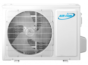
ABSCI4H4S12 is the 21 SEER 12,000 Btu outdoor unit of Blue Series 2.
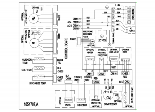
Wiring Diagram
PCB Printed Diagram
| Number | Description |
|---|---|
| 1 | Terminal of Compressor U/V/W Phase |
| 2 | Terminal of Reactor |
| 3 | Terminal of Reactor |
| 4 | Terminal of Signal Wire to Terminal Block |
| 5 | Terminal of Neutral Wire to Terminal Block |
| 6 | Terminal of Neutral Wire to Terminal Block |
| 7 | Cool Valve Terminal |
| 8 | Terminal of AC Fan |
| 9 | 4-way Valve Terminal |
| 10 | Terminal of Electronic Expansion Valve |
| 11 | Outdoor Ambient Temperature Sensor |
| 12 | Outdoor Pipe Temperature Sensor |
| 13 | Compressor Discharge Temperature Sensor |
| 14 | Terminal of Compressor Overload Protector |
| 15 | Over Pressure Sensor |
| 16 | Terminal of DC Fan |
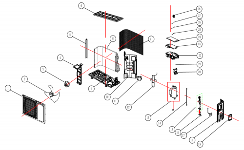
Exploded View and Parts List
| Number | Part Name | Part Number |
|---|---|---|
| 1 | Panel Parts | 1902781 |
| 2 | Propeller Fan Blade | 1556766 |
| 3 | Fan Motor | 1902991 |
| 4 | Motor Supporter Assy | 1902996 |
| 5 | Mounting Plate | 1902529 |
| 6 | Upper Board | 1902782 |
| 7 | Back Guard | 1854579 |
| 8 | Condenser Assembly | 1904314 |
| 9 | Base Holder Part | 1851356 |
| 10 | Clapboard | 1847982 |
| 11 | PFC Inductance | 1893020 |
| 12 | Pipe Assy | 1856291 |
| 13 | Compressor | 1821191 |
| 14 | Compressor Connect Wire | 1847142 |
| 15 | Capillary Assembly | 1856290 |
| 16 | 2-way Valve | 1844583 |
| 17 | 3-Way Valve | 1856322 |
| 18 | Right Side Board | 1902770 |
| 19 | Wiring Distribution Cover Assy | 1902530 |
| 20 | Connecting Board | 1902438 |
| 21 | Wire Terminal Board | 1852124 |
| 22 | Electric Box | 1841985 |
| 23 | Outdoor Main Control Board Component1 | 1903082 |
| 24 | Electric Box Cover | 1546706 |
| 25 | Temperature Sensor | 1472663 |
| 26 | Temperature Sensor | 1511780 |
| 27 | Temperature Sensor | 1831029 |
| 28 | Sensor Mounting Plate | 1546721 |
1ODU control board had a revision in March 2018.
Piping Sizes
| Liquid Side | Gas Side |
|---|---|
| 1/4" | 3/8" |


