Difference between revisions of "A13CH4H4G24"
From Technical Support Wiki
| (6 intermediate revisions by the same user not shown) | |||
| Line 1: | Line 1: | ||
| − | A13CH4H4G24 is the 13 SEER 24,000 Btu mini split in the ''Bronze Series'' line. | + | A13CH4H4G24 is the 13 SEER 24,000 Btu mini split in the ''[[Bronze Series]]'' line. [[File:Bronze-condenser.png|right|thumb|''Bronze Series'' condenser]] |
== Wiring Diagram == | == Wiring Diagram == | ||
| − | == Piping | + | Please click [[:File:DIAGRAM_OF_POWER_INSTALLATION_AND_CONNECTIONS_ON_18_24_13_SEER.pdf|here]] for a PDF of the power and signal cable wiring diagram. |
| − | == Parts == | + | == Piping Sizes == |
| + | {| class="wikitable" | ||
| + | ! Liquid Side | ||
| + | ! Gas Side | ||
| + | |- | ||
| + | | 3/8" | ||
| + | | 5/8" | ||
| + | |} | ||
| + | == Exploded View and Parts List == | ||
| + | [[File:Bronze-18k-24k-ODU-EV.jpg|thumb|500px| A13CH4H4G24 Exploded View]] | ||
| + | {| class="wikitable" | ||
| + | ! Number | ||
| + | ! Part Name | ||
| + | |- | ||
| + | | 1 | ||
| + | | Front Grill | ||
| + | |- | ||
| + | | 2 | ||
| + | | Grill Clip | ||
| + | |- | ||
| + | | 3 | ||
| + | | Front Plate | ||
| + | |- | ||
| + | | 4 | ||
| + | | Nut | ||
| + | |- | ||
| + | | 5 | ||
| + | | Gasket | ||
| + | |- | ||
| + | | 6 | ||
| + | | Axial Flow Fan | ||
| + | |- | ||
| + | | 7 | ||
| + | | Motor | ||
| + | |- | ||
| + | | 8 | ||
| + | | Motor Support | ||
| + | |- | ||
| + | | 9 | ||
| + | | Left Protect Net | ||
| + | |- | ||
| + | | 10 | ||
| + | | Pillar | ||
| + | |- | ||
| + | | 11 | ||
| + | | Partition Board | ||
| + | |- | ||
| + | | 12 | ||
| + | | PU Sponge | ||
| + | |- | ||
| + | | 13 | ||
| + | | Top Panel | ||
| + | |- | ||
| + | | 14 | ||
| + | | Small Handle | ||
| + | |- | ||
| + | | 15 | ||
| + | | Fan Capacitor | ||
| + | |- | ||
| + | | 16 | ||
| + | | Electric Installation Board | ||
| + | |- | ||
| + | | 17 | ||
| + | | Capacitor Clamp | ||
| + | |- | ||
| + | | 18 | ||
| + | | Fan Capacitor | ||
| + | |- | ||
| + | | 19 | ||
| + | | Terminal Board | ||
| + | |- | ||
| + | | 20 | ||
| + | | Wire Clip | ||
| + | |- | ||
| + | | 21 | ||
| + | | PU Sponge | ||
| + | |- | ||
| + | | 22 | ||
| + | | Condenser | ||
| + | |- | ||
| + | | 23 | ||
| + | | Rear Grill | ||
| + | |- | ||
| + | | 24 | ||
| + | | 4-Way Valve Assembly | ||
| + | |- | ||
| + | | 25 | ||
| + | | Capillary Assembly | ||
| + | |- | ||
| + | | 26 | ||
| + | | Right Panel | ||
| + | |- | ||
| + | | 27 | ||
| + | | Large Handle | ||
| + | |- | ||
| + | | 28 | ||
| + | | Discharge Pipe | ||
| + | |- | ||
| + | | 29 | ||
| + | | Anti-Vibration Pad | ||
| + | |- | ||
| + | | 30 | ||
| + | | Suction Pipe | ||
| + | |- | ||
| + | | 31 | ||
| + | | Low-Pressure Valve | ||
| + | |- | ||
| + | | 32 | ||
| + | | High-Pressure Valve | ||
| + | |- | ||
| + | | 33 | ||
| + | | Valve Installation Plate | ||
| + | |- | ||
| + | | 34 | ||
| + | | Compressor Power Cord | ||
| + | |- | ||
| + | | 35 | ||
| + | | Anti-Vibration Pad for the Compressor | ||
| + | |- | ||
| + | | 36 | ||
| + | | Compressor | ||
| + | |- | ||
| + | | 37 | ||
| + | | Compressor Terminal Cover | ||
| + | |- | ||
| + | | 38 | ||
| + | | Nut | ||
| + | |- | ||
| + | | 39 | ||
| + | | Gasket | ||
| + | |- | ||
| + | | 40 | ||
| + | | Base | ||
| + | |- | ||
| + | | 41 | ||
| + | | Maintenance Plate | ||
| + | |} | ||
== Accessories == | == Accessories == | ||
| + | *[[Wall Bracket (QBR-19.5)]] | ||
| + | *[[Universal Remote (QTH-4000)]] | ||
Latest revision as of 20:43, 17 December 2013
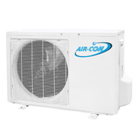
A13CH4H4G24 is the 13 SEER 24,000 Btu mini split in the Bronze Series line.
Wiring Diagram
Please click here for a PDF of the power and signal cable wiring diagram.
Piping Sizes
| Liquid Side | Gas Side |
|---|---|
| 3/8" | 5/8" |
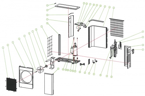
Exploded View and Parts List
| Number | Part Name |
|---|---|
| 1 | Front Grill |
| 2 | Grill Clip |
| 3 | Front Plate |
| 4 | Nut |
| 5 | Gasket |
| 6 | Axial Flow Fan |
| 7 | Motor |
| 8 | Motor Support |
| 9 | Left Protect Net |
| 10 | Pillar |
| 11 | Partition Board |
| 12 | PU Sponge |
| 13 | Top Panel |
| 14 | Small Handle |
| 15 | Fan Capacitor |
| 16 | Electric Installation Board |
| 17 | Capacitor Clamp |
| 18 | Fan Capacitor |
| 19 | Terminal Board |
| 20 | Wire Clip |
| 21 | PU Sponge |
| 22 | Condenser |
| 23 | Rear Grill |
| 24 | 4-Way Valve Assembly |
| 25 | Capillary Assembly |
| 26 | Right Panel |
| 27 | Large Handle |
| 28 | Discharge Pipe |
| 29 | Anti-Vibration Pad |
| 30 | Suction Pipe |
| 31 | Low-Pressure Valve |
| 32 | High-Pressure Valve |
| 33 | Valve Installation Plate |
| 34 | Compressor Power Cord |
| 35 | Anti-Vibration Pad for the Compressor |
| 36 | Compressor |
| 37 | Compressor Terminal Cover |
| 38 | Nut |
| 39 | Gasket |
| 40 | Base |
| 41 | Maintenance Plate |

