Difference between revisions of "ACZEM4H4R18"
From Technical Support Wiki
| (4 intermediate revisions by the same user not shown) | |||
| Line 42: | Line 42: | ||
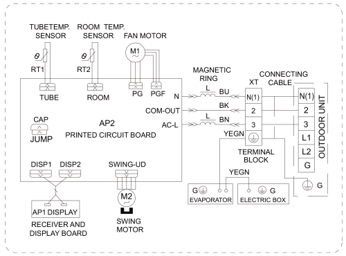
[[File:Blue-18k-IDU-WD.png|none|thumb|500px|ACZEM4H4R18 Wiring Diagram]] | [[File:Blue-18k-IDU-WD.png|none|thumb|500px|ACZEM4H4R18 Wiring Diagram]] | ||
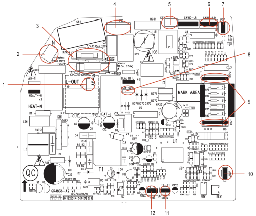
== PCB Printed Diagram == | == PCB Printed Diagram == | ||
| − | [[File:Blue- | + | [[File:Blue-18k-IDU-PCB.png|right|thumb|500px|ACZEM4H4R18 PCB Printed Diagram]] |
{| class="wikitable" | {| class="wikitable" | ||
! Number | ! Number | ||
| Line 51: | Line 51: | ||
|- | |- | ||
| 2 | | 2 | ||
| − | | | + | | Neutral wire interface |
|- | |- | ||
| 3 | | 3 | ||
| − | | | + | | Fuse |
|- | |- | ||
| 4 | | 4 | ||
| − | | PG motor | + | | PG motor |
|- | |- | ||
| 5 | | 5 | ||
| − | | | + | | Auto button |
|- | |- | ||
| 6 | | 6 | ||
| − | | | + | | Up and down swing terminal interface |
|- | |- | ||
| 7 | | 7 | ||
| − | | | + | | PG feedback |
|- | |- | ||
| 8 | | 8 | ||
| − | | | + | | IDU and ODU communication interface |
|- | |- | ||
| 9 | | 9 | ||
| − | | Display interface | + | | Display terminal interface |
|- | |- | ||
| 10 | | 10 | ||
| + | | Jumper | ||
| + | |- | ||
| + | | 11 | ||
| Ambient temperature sensor | | Ambient temperature sensor | ||
|- | |- | ||
| − | | | + | | 12 |
| Tube temperature sensor | | Tube temperature sensor | ||
|} | |} | ||
| Line 89: | Line 92: | ||
<br /> | <br /> | ||
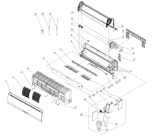
== Exploded View and Parts List == | == Exploded View and Parts List == | ||
| − | [[File:Blue- | + | [[File:Blue-18k-IDU-EV.png|center|thumb|500px|ACZEM4H4R18 Exploded View]] |
{| class="wikitable" | {| class="wikitable" | ||
! Number | ! Number | ||
! Part Name | ! Part Name | ||
| + | ! Part Number | ||
|- | |- | ||
| 1 | | 1 | ||
| Front Panel Sub-Assy | | Front Panel Sub-Assy | ||
| + | | 20012286_L14385 | ||
|- | |- | ||
| 2 | | 2 | ||
| Filter Sub-Assy | | Filter Sub-Assy | ||
| + | | 1112208901 | ||
|- | |- | ||
| 3 | | 3 | ||
| − | | | + | | Screw Cover |
| + | | 24252016 | ||
|- | |- | ||
| 4 | | 4 | ||
| − | | | + | | Front Case Sub-Assy |
| + | | 20022172 | ||
|- | |- | ||
| 5 | | 5 | ||
| − | | | + | | Guide Louver |
| + | | 10512115 | ||
|- | |- | ||
| 6 | | 6 | ||
| − | | | + | | Air Louver 1 |
| + | | 10512708 | ||
|- | |- | ||
| 7 | | 7 | ||
| − | | | + | | Helicoid Tongue |
| + | | 26112238 | ||
|- | |- | ||
| 8 | | 8 | ||
| − | | | + | | Left Axile Bush |
| + | | 10512037 | ||
|- | |- | ||
| 9 | | 9 | ||
| − | | | + | | Rear Case Assy |
| + | | 22202128 | ||
|- | |- | ||
| 10 | | 10 | ||
| − | | | + | | Rubber Plug (Water Tray) |
| + | | 76712012 | ||
|- | |- | ||
| 11 | | 11 | ||
| − | | | + | | O-Gasket of Cross Fan Bearing |
| + | | 76512203 | ||
|- | |- | ||
| 12 | | 12 | ||
| − | | O-Gasket Sub-Assy of Bearing | + | | O-Gasket Sub-Assy of Bearing |
| + | | 7651205102 | ||
|- | |- | ||
| 13 | | 13 | ||
| − | | | + | | Evaporator Support |
| + | | 24212133 | ||
|- | |- | ||
| 14 | | 14 | ||
| − | | Evaporator | + | | Evaporator Assy |
| + | | 01002000028 | ||
|- | |- | ||
| 15 | | 15 | ||
| − | | | + | | Wall Mounting Frame |
| + | | 01252218 | ||
|- | |- | ||
| 16 | | 16 | ||
| − | | | + | | Cross Flow Fan |
| + | | 10352019 | ||
|- | |- | ||
| 17 | | 17 | ||
| − | | | + | | Motor Press Plate |
| + | | 26112494 | ||
|- | |- | ||
| 18 | | 18 | ||
| − | | | + | | Fan Motor |
| + | | 1501214601 | ||
|- | |- | ||
| 19 | | 19 | ||
| − | | | + | | Pipe Clamp |
| + | | 26112164 | ||
|- | |- | ||
| 20 | | 20 | ||
| − | | | + | | Drainage Hose |
| + | | 05230014 | ||
|- | |- | ||
| 21 | | 21 | ||
| − | | | + | | Step Motor |
| + | | 15012086 | ||
|- | |- | ||
| 22 | | 22 | ||
| − | | | + | | Crank |
| + | | 10582070 | ||
|- | |- | ||
| 23 | | 23 | ||
| − | | | + | | Display Board |
| + | | 30565093 | ||
|- | |- | ||
| 24 | | 24 | ||
| − | | | + | | Air Louver 2 |
| + | | 10512709 | ||
|- | |- | ||
| 25 | | 25 | ||
| − | | | + | | Electric Box Assy |
| + | | 10000200507 | ||
|- | |- | ||
| 26 | | 26 | ||
| − | | | + | | Lower Shield of Electric Box |
| + | | 01592091 | ||
|- | |- | ||
| 27 | | 27 | ||
| Electric Box | | Electric Box | ||
| + | | 2011210802 | ||
|- | |- | ||
| 28 | | 28 | ||
| − | | | + | | Axile Bush |
| + | | 10542036 | ||
|- | |- | ||
| 29 | | 29 | ||
| Terminal Board | | Terminal Board | ||
| + | | 42011233 | ||
|- | |- | ||
| 30 | | 30 | ||
| − | | | + | | Jumper |
| + | | 4202300109 | ||
|- | |- | ||
| 31 | | 31 | ||
| − | | | + | | Electric Box Cover 2 |
| + | | 2011208112 | ||
|- | |- | ||
| 32 | | 32 | ||
| − | | | + | | Main Board |
| + | | 30138000014 | ||
|- | |- | ||
| 33 | | 33 | ||
| − | | | + | | Shield Cover of Electric Box |
| + | | 01592092 | ||
|- | |- | ||
| 34 | | 34 | ||
| − | | | + | | Electric Box Cover 1 |
| + | | 2012215401 | ||
|- | |- | ||
| 35 | | 35 | ||
| − | | | + | | Remote Controller |
| + | | 30510092_L14385 | ||
|- | |- | ||
| 36 | | 36 | ||
| − | | | + | | Temperature Sensor |
| + | | 390000453 | ||
|- | |- | ||
| 37 | | 37 | ||
| − | | | + | | Temperature Sensor |
| − | + | | 390000599 | |
| − | |||
| − | |||
| − | |||
| − | |||
| − | |||
| − | | | ||
| − | |||
| − | |||
|} | |} | ||
Latest revision as of 13:58, 8 April 2022
ACZEM4H4R18 is the 15 SEER 18,000 Btu indoor unit of the Blue Series.
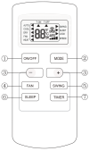
Remote Control
| # | Name | Description |
| 1 | ON/OFF | Press to start or stop operation. |
| 2 | MODE | Press to select operation mode (Auto/Cool/Dry/Fan/Heat). |
| 3 | + (Raise) | Press to raise the temperature setting. |
| 3 | - (Lower) | Press to lower the temperature setting. |
| 4 | FAN | Press to set fan speed. Rotates between Auto and Speeds 1-4. |
| 5 | SWING | Press to set swing angle. |
| 6 | SLEEP | Press to turn on sleep function. |
| 7 | TIMER | Manage the on and off timer with this button. |
Wiring Diagram
PCB Printed Diagram
| Number | Description |
|---|---|
| 1 | Live wire interface |
| 2 | Neutral wire interface |
| 3 | Fuse |
| 4 | PG motor |
| 5 | Auto button |
| 6 | Up and down swing terminal interface |
| 7 | PG feedback |
| 8 | IDU and ODU communication interface |
| 9 | Display terminal interface |
| 10 | Jumper |
| 11 | Ambient temperature sensor |
| 12 | Tube temperature sensor |
Exploded View and Parts List
| Number | Part Name | Part Number |
|---|---|---|
| 1 | Front Panel Sub-Assy | 20012286_L14385 |
| 2 | Filter Sub-Assy | 1112208901 |
| 3 | Screw Cover | 24252016 |
| 4 | Front Case Sub-Assy | 20022172 |
| 5 | Guide Louver | 10512115 |
| 6 | Air Louver 1 | 10512708 |
| 7 | Helicoid Tongue | 26112238 |
| 8 | Left Axile Bush | 10512037 |
| 9 | Rear Case Assy | 22202128 |
| 10 | Rubber Plug (Water Tray) | 76712012 |
| 11 | O-Gasket of Cross Fan Bearing | 76512203 |
| 12 | O-Gasket Sub-Assy of Bearing | 7651205102 |
| 13 | Evaporator Support | 24212133 |
| 14 | Evaporator Assy | 01002000028 |
| 15 | Wall Mounting Frame | 01252218 |
| 16 | Cross Flow Fan | 10352019 |
| 17 | Motor Press Plate | 26112494 |
| 18 | Fan Motor | 1501214601 |
| 19 | Pipe Clamp | 26112164 |
| 20 | Drainage Hose | 05230014 |
| 21 | Step Motor | 15012086 |
| 22 | Crank | 10582070 |
| 23 | Display Board | 30565093 |
| 24 | Air Louver 2 | 10512709 |
| 25 | Electric Box Assy | 10000200507 |
| 26 | Lower Shield of Electric Box | 01592091 |
| 27 | Electric Box | 2011210802 |
| 28 | Axile Bush | 10542036 |
| 29 | Terminal Board | 42011233 |
| 30 | Jumper | 4202300109 |
| 31 | Electric Box Cover 2 | 2011208112 |
| 32 | Main Board | 30138000014 |
| 33 | Shield Cover of Electric Box | 01592092 |
| 34 | Electric Box Cover 1 | 2012215401 |
| 35 | Remote Controller | 30510092_L14385 |
| 36 | Temperature Sensor | 390000453 |
| 37 | Temperature Sensor | 390000599 |


