Difference between revisions of "ACZCH4H4R09"
From Technical Support Wiki
| (7 intermediate revisions by the same user not shown) | |||
| Line 1: | Line 1: | ||
ACZCI4H4R09 is the 15 SEER 9,000 Btu outdoor unit of the ''[[Blue Series]]''. [[File:Plat-cond-2.png|right|thumb|''Blue Series'' condenser (9k)]] | ACZCI4H4R09 is the 15 SEER 9,000 Btu outdoor unit of the ''[[Blue Series]]''. [[File:Plat-cond-2.png|right|thumb|''Blue Series'' condenser (9k)]] | ||
== Wiring Diagram == | == Wiring Diagram == | ||
| − | [[File: | + | [[File:Blue-9-12k-ODU-WD.png|none|thumb|500px|ACZCI4H4R09 Wiring Diagram]] |
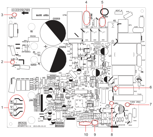
| + | == PCB Printed Diagram == | ||
| + | [[File:Blue-9-12k-ODU-PCB.png|right|thumb|500px|ACZCI4H4R09 PCB Diagram]] | ||
| + | {| class="wikitable" | ||
| + | ! Number | ||
| + | ! Description | ||
| + | |- | ||
| + | | 1 | ||
| + | | Compressor UVW three phases | ||
| + | |- | ||
| + | | 2 | ||
| + | | Reactor interface 2 | ||
| + | |- | ||
| + | | 3 | ||
| + | | Reactor interface 1 | ||
| + | |- | ||
| + | | 4 | ||
| + | | Fan interface | ||
| + | |- | ||
| + | | 5 | ||
| + | | 4-way valve interface | ||
| + | |- | ||
| + | | 6 | ||
| + | | Power supply neutral wire | ||
| + | |- | ||
| + | | 7 | ||
| + | | Power supply neutral wire | ||
| + | |- | ||
| + | | 8 | ||
| + | | Communication wire | ||
| + | |- | ||
| + | | 9 | ||
| + | | Overload input | ||
| + | |- | ||
| + | | 10 | ||
| + | | Temperature sensor interface | ||
| + | |} | ||
| + | <br /> | ||
| + | <br /> | ||
| + | <br /> | ||
| + | <br /> | ||
| + | <br /> | ||
| + | <br /> | ||
| + | <br /> | ||
| + | <br /> | ||
| + | <br /> | ||
| + | <br /> | ||
| + | <br /> | ||
| + | <br /> | ||
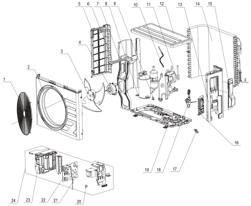
== Exploded View and Parts List == | == Exploded View and Parts List == | ||
| − | [[File:Blue-9-12k-ODU- | + | [[File:Blue-9-12k-ODU-EV.png|left|thumb|500px|ACZCI4H4R09 Exploded View]] |
{| class="wikitable" | {| class="wikitable" | ||
! Number | ! Number | ||
| Line 15: | Line 63: | ||
|- | |- | ||
| 3 | | 3 | ||
| − | | | + | | Axial Flow Fan Sub-Assy |
|- | |- | ||
| 4 | | 4 | ||
| − | | | + | | Fan Motor |
|- | |- | ||
| 5 | | 5 | ||
| − | | | + | | Left Side Plate |
|- | |- | ||
| 6 | | 6 | ||
| − | | | + | | Motor Support |
|- | |- | ||
| 7 | | 7 | ||
| − | | | + | | Clapboard |
|- | |- | ||
| 8 | | 8 | ||
| − | | | + | | Compressor and Fittings |
|- | |- | ||
| 9 | | 9 | ||
| − | | | + | | Compressor Overload Protector (External) |
|- | |- | ||
| 10 | | 10 | ||
| − | | | + | | Electric Heater (Compressor) |
|- | |- | ||
| 11 | | 11 | ||
| − | | | + | | 4-Way Valve Assy |
|- | |- | ||
| 12 | | 12 | ||
| − | | | + | | Top Cover Sub-Assy |
|- | |- | ||
| 13 | | 13 | ||
| − | | Right Side Plate | + | | Right Side Plate Sub-Assy |
|- | |- | ||
| 14 | | 14 | ||
| − | | | + | | Condenser Assy |
|- | |- | ||
| 15 | | 15 | ||
| − | | | + | | Handle |
|- | |- | ||
| 16 | | 16 | ||
| − | | | + | | Valve Support |
|- | |- | ||
| 17 | | 17 | ||
| − | | | + | | Drainage Joint |
|- | |- | ||
| 18 | | 18 | ||
| − | | | + | | Cut Off Valve Assy |
|- | |- | ||
| 19 | | 19 | ||
| − | | | + | | Chassis Sub-Assy |
|- | |- | ||
| 20 | | 20 | ||
| − | | | + | | Capacitor CBB61 |
|- | |- | ||
| 21 | | 21 | ||
| − | | | + | | Temperature Sensor |
|- | |- | ||
| 22 | | 22 | ||
| − | | | + | | Main Board |
|- | |- | ||
| 23 | | 23 | ||
| − | | | + | | Electric Box Sub-Assy |
|- | |- | ||
| 24 | | 24 | ||
| − | |||
| − | |||
| − | |||
| − | |||
| − | |||
| − | |||
| − | |||
| − | |||
| − | |||
| − | |||
| − | |||
| − | |||
| − | |||
| − | |||
| − | |||
| − | |||
| − | |||
| − | |||
| − | |||
| − | |||
| − | |||
| − | |||
| − | |||
| − | |||
| − | |||
| − | |||
| − | |||
| − | |||
| − | |||
| − | |||
| − | |||
| − | |||
| − | |||
| − | |||
| − | |||
| − | |||
| − | |||
| − | |||
| − | |||
| − | |||
| − | |||
| − | |||
| Electric Box Assy | | Electric Box Assy | ||
| − | |||
| − | |||
| − | |||
|} | |} | ||
== Piping Sizes == | == Piping Sizes == | ||
Latest revision as of 14:14, 11 April 2014
ACZCI4H4R09 is the 15 SEER 9,000 Btu outdoor unit of the Blue Series.
Wiring Diagram
PCB Printed Diagram
| Number | Description |
|---|---|
| 1 | Compressor UVW three phases |
| 2 | Reactor interface 2 |
| 3 | Reactor interface 1 |
| 4 | Fan interface |
| 5 | 4-way valve interface |
| 6 | Power supply neutral wire |
| 7 | Power supply neutral wire |
| 8 | Communication wire |
| 9 | Overload input |
| 10 | Temperature sensor interface |
Exploded View and Parts List
| Number | Part Name |
|---|---|
| 1 | Front Grill |
| 2 | Cabinet |
| 3 | Axial Flow Fan Sub-Assy |
| 4 | Fan Motor |
| 5 | Left Side Plate |
| 6 | Motor Support |
| 7 | Clapboard |
| 8 | Compressor and Fittings |
| 9 | Compressor Overload Protector (External) |
| 10 | Electric Heater (Compressor) |
| 11 | 4-Way Valve Assy |
| 12 | Top Cover Sub-Assy |
| 13 | Right Side Plate Sub-Assy |
| 14 | Condenser Assy |
| 15 | Handle |
| 16 | Valve Support |
| 17 | Drainage Joint |
| 18 | Cut Off Valve Assy |
| 19 | Chassis Sub-Assy |
| 20 | Capacitor CBB61 |
| 21 | Temperature Sensor |
| 22 | Main Board |
| 23 | Electric Box Sub-Assy |
| 24 | Electric Box Assy |
Piping Sizes
| Liquid Side | Gas Side |
|---|---|
| 1/4" | 3/8" |


