Difference between revisions of "ATUEM4H1S09"
From Technical Support Wiki
| (2 intermediate revisions by the same user not shown) | |||
| Line 1: | Line 1: | ||
| − | ATUEM4H1S09 is the 19 SEER 9,000 Btu indoor unit of ''[[Titanium Series]]''. [[File: | + | ATUEM4H1S09 is the 19 SEER 9,000 Btu indoor unit of ''[[Titanium Series]]''. [[File:115V-IDU-1.png|right|thumb|''Titanium Series'' evaporator (9k)]] |
== Remote Control == | == Remote Control == | ||
[[File:Blue-series-2-remote.png|left|thumb|200px|Remote Control]] | [[File:Blue-series-2-remote.png|left|thumb|200px|Remote Control]] | ||
| Line 67: | Line 67: | ||
== PCB Printed Diagram == | == PCB Printed Diagram == | ||
| − | [[File:Blue2-9-12k-IDU-PCB.png|right|thumb|500px| | + | [[File:Blue2-9-12k-IDU-PCB.png|right|thumb|500px|ATUEM4H1S09 PCB Printed Diagram]] |
{| class="wikitable" | {| class="wikitable" | ||
! Number | ! Number | ||
| Line 106: | Line 106: | ||
== Exploded View and Parts List == | == Exploded View and Parts List == | ||
| − | [[File: | + | [[File:Titanium-9k-IDU-EV.png|left|thumb|500px|ATUEM4H1S09 Exploded View]] |
{| class="wikitable" | {| class="wikitable" | ||
! Number | ! Number | ||
Latest revision as of 15:08, 10 November 2017
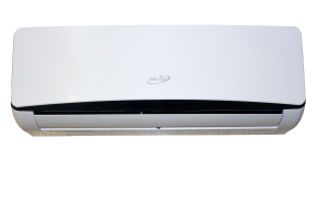
ATUEM4H1S09 is the 19 SEER 9,000 Btu indoor unit of Titanium Series.
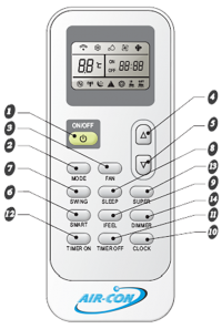
Remote Control
| # | Name | Description |
| 1 | ON/OFF | Press to start or stop operation. |
| 2 | MODE | Press to select operation mode (Auto/Cool/Dry/Fan/Heat). |
| 3 | FAN | Used to select the fan speed in sequence: auto, high, medium, or low. |
| 4 | ROOM TEMPERATURE SETTING | Press to raise the temperature setting. Can also be used to adjust the timer and adjust the current time. |
| 5 | ROOM TEMPERATURE SETTING | Press to lower the temperature setting. Can also be used to adjust the timer and adjust the current time. |
| 6 | SMART | Adjust smart settings. |
| 7 | SWING | Used to stop or start vertical adjustment louver swinging and set the desired up/down airflow direction. |
| 8 | SLEEP | Used to set or cancel Sleep Mode operation. |
| 9 | IFEEL | Used to set IFEEL operation. |
| 10 | CLOCK | Used to set the current time. |
| 11 | TIMER ON | Used to turn the timer function on. |
| 12 | TIMER OFF | Used to turn the timer function off. |
| 13 | SUPER | Used to start/stop the super cool/heat function. (Super cooling operates at high fan speed with a default 64 F temperature setting. Super heating operates at high fan speed with a default 89 F temperature setting.) |
| 14 | DIMMER | Pressing this button will dim the display on the indoor unit. Pressing any button will reverse the dimmer. |
Wiring Diagram
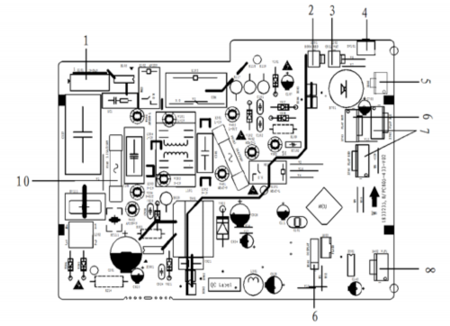
PCB Printed Diagram
| Number | Description |
|---|---|
| 1 | PG Motor Interface |
| 2 | Room temperature sensor |
| 3 | Pipe temperature sensor |
| 4 | Switch buton |
| 5 | Feedback from PG Motor |
| 6 | Up & down swing |
| 7 | Left & right swing |
| 8 | Wiring control or Wifi interface |
| 9 | Display interface |
| 10 | Protective tube |
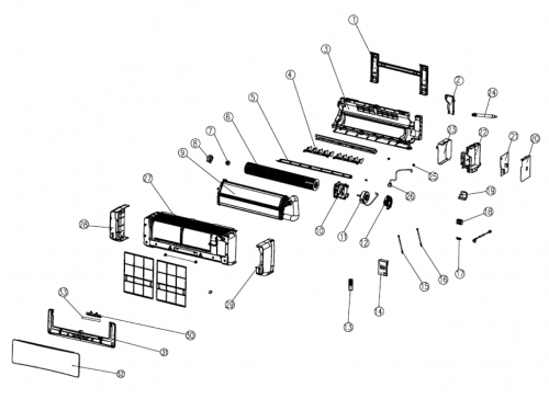
Exploded View and Parts List
| Number | Part Name |
|---|---|
| 1 | Installation Plate Assy |
| 2 | Baffle |
| 3 | Base Holder Part |
| 4 | Vertical Level Vane |
| 5 | Level Vane |
| 6 | Cross Flow Fan Blade |
| 7 | Bearing |
| 8 | Baffle |
| 9 | Refrigeration System |
| 10 | Motor Guard |
| 11 | Fan Motor |
| 12 | Motor Cover |
| 13 | Remote Controller |
| 14 | Electric Box Cover |
| 15 | Temperature Sensor |
| 16 | Temperature Sensor |
| 17 | Over Clamp |
| 18 | Wire Terminal Board |
| 19 | Electric Box Cover |
| 20 | Electric Joint Box Plate |
| 21 | Indoor Main Control Board Component |
| 22 | Electric Box |
| 23 | Electric Joint Box Plate |
| 24 | Water Pipe Parts |
| 25 | Axis Sheath |
| 26 | Step Motor |
| 27 | Shell |
| 28 | Ornamental Part |
| 29 | Ornamental Part |
| 30 | Display Component |
| 31 | Ornamental Part |
| 32 | Panel |
| 33 | Display Film |


