Difference between revisions of "AMTCM4H4R30"
From Technical Support Wiki
| (2 intermediate revisions by the same user not shown) | |||
| Line 11: | Line 11: | ||
|- | |- | ||
| 1 | | 1 | ||
| − | | | + | | Coping |
|- | |- | ||
| 2 | | 2 | ||
| − | | | + | | Left Handle |
|- | |- | ||
| 3 | | 3 | ||
| − | | Left | + | | Left Side Plate |
|- | |- | ||
| 4 | | 4 | ||
| − | | | + | | Fan Motor |
|- | |- | ||
| 5 | | 5 | ||
| − | | | + | | Axial Flow Fan |
|- | |- | ||
| 6 | | 6 | ||
| − | | | + | | Cabinet |
|- | |- | ||
| 7 | | 7 | ||
| − | | | + | | Front Grill |
|- | |- | ||
| 8 | | 8 | ||
| − | | | + | | Front Side Plate |
|- | |- | ||
| 9 | | 9 | ||
| − | | | + | | Electrical Heater |
|- | |- | ||
| 10 | | 10 | ||
| − | | | + | | Chassis Sub-Assy |
|- | |- | ||
| 11 | | 11 | ||
| − | | | + | | Compressor |
|- | |- | ||
| 12 | | 12 | ||
| − | | | + | | Electric Heater (Compressor) |
|- | |- | ||
| 13 | | 13 | ||
| − | | | + | | Compressor Gasket |
|- | |- | ||
| 14 | | 14 | ||
| − | | | + | | Sensor Sub-Assy |
|- | |- | ||
| 15 | | 15 | ||
| − | | | + | | Compressor Overload Protector (External) |
|- | |- | ||
| 16 | | 16 | ||
| − | | | + | | Valve Support Assy |
|- | |- | ||
| 17 | | 17 | ||
| − | | | + | | Strainer A |
|- | |- | ||
| 18 | | 18 | ||
| − | | | + | | Electronic Expansion Valve |
|- | |- | ||
| 19 | | 19 | ||
| − | | | + | | Electric Expand Valve Fitting |
|- | |- | ||
| 20 | | 20 | ||
| − | | | + | | Cut Off Valve |
|- | |- | ||
| 21 | | 21 | ||
| − | | | + | | Cut Off Valve |
|- | |- | ||
| 22 | | 22 | ||
| − | | | + | | Wiring Cover Sub-Assy |
|- | |- | ||
| 23 | | 23 | ||
| − | | | + | | Handle Assy |
|- | |- | ||
| 24 | | 24 | ||
| − | | | + | | Right Side Plate |
|- | |- | ||
| 25 | | 25 | ||
| − | | | + | | Electric Expand Valve Fitting |
|- | |- | ||
| 26 | | 26 | ||
| − | | | + | | Electric Expand Valve Fitting |
|- | |- | ||
| 27 | | 27 | ||
| Line 92: | Line 92: | ||
|- | |- | ||
| 28 | | 28 | ||
| − | | | + | | Electric Expand Valve Fitting |
|- | |- | ||
| 29 | | 29 | ||
| − | | | + | | Bidirection Strainer |
|- | |- | ||
| 30 | | 30 | ||
| − | | | + | | Gas-Liquid Separator Assy |
|- | |- | ||
| 31 | | 31 | ||
| − | | | + | | Reactor |
|- | |- | ||
| 32 | | 32 | ||
| − | | | + | | Rear Grill |
|- | |- | ||
| 33 | | 33 | ||
| − | | | + | | Clapboard |
|- | |- | ||
| 34 | | 34 | ||
| − | | | + | | Cable Cross Loop |
|- | |- | ||
| 35 | | 35 | ||
| − | | | + | | Condenser Assy |
|- | |- | ||
| 36 | | 36 | ||
| Line 119: | Line 119: | ||
|- | |- | ||
| 37 | | 37 | ||
| − | | | + | | Condenser Assy |
|- | |- | ||
| 38 | | 38 | ||
| − | | | + | | Pressure Protect Switch |
|- | |- | ||
| 39 | | 39 | ||
| − | | | + | | 4-Way Valve |
|- | |- | ||
| 40 | | 40 | ||
| − | | | + | | 4-Way Valve Assy |
|- | |- | ||
| 41 | | 41 | ||
| − | | | + | | Magnet Coil |
|- | |- | ||
| 42 | | 42 | ||
| − | | | + | | Electric Box Assy |
|- | |- | ||
| 43 | | 43 | ||
| − | | | + | | Wire Clamp |
|- | |- | ||
| 44 | | 44 | ||
| + | | Terminal board | ||
| + | |- | ||
| + | | 45 | ||
| + | | Wire Clamp | ||
| + | |- | ||
| + | | 46 | ||
| + | | Insulation Gasket | ||
| + | |- | ||
| + | | 47 | ||
| + | | Terminal Board | ||
| + | |- | ||
| + | | 48 | ||
| + | | Magnetic Ring | ||
| + | |- | ||
| + | | 49 | ||
| + | | Cable Cross Loop | ||
| + | |- | ||
| + | | 50 | ||
| Main Board | | Main Board | ||
|- | |- | ||
| − | | | + | | 51 |
| − | | Electric Box | + | | Electric Box |
| + | |- | ||
| + | | 52 | ||
| + | | Radiator | ||
| + | |- | ||
| + | | 53 | ||
| + | | Sensor Sub-Assy | ||
|} | |} | ||
| Line 150: | Line 174: | ||
! Liquid Side | ! Liquid Side | ||
! Gas Side | ! Gas Side | ||
| − | ! Evaporators | + | ! Wall Mount Evaporators (A16) |
| + | ! Wall Mount Evaporators (AMT) | ||
|- | |- | ||
| 1/4" | | 1/4" | ||
| 3/8" | | 3/8" | ||
| A16EW4H4R09 <br />A16EW4H4R12 | | A16EW4H4R09 <br />A16EW4H4R12 | ||
| + | | AMTEM4H4R09 <br />AMTEM4H4R12 | ||
|- | |- | ||
| 1/4" | | 1/4" | ||
| 1/2" | | 1/2" | ||
| A16EW4H4R18 | | A16EW4H4R18 | ||
| + | | AMTEM4H4R18 | ||
| + | |- | ||
| + | | 3/8" | ||
| + | | 5/8" | ||
| + | | A16EW4H4R24 | ||
| + | | - | ||
|} | |} | ||
== Accessories == | == Accessories == | ||
*[[Wall Bracket (QBR-19.5)]] | *[[Wall Bracket (QBR-19.5)]] | ||
*[[Universal Remote (QTH-4000)]] | *[[Universal Remote (QTH-4000)]] | ||
Latest revision as of 14:45, 6 November 2019
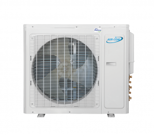
AMTCM4H4R30 is the 21 SEER, 30,000 BTU quad zone multi split unit.
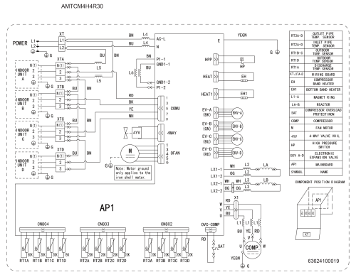
Wiring Diagram
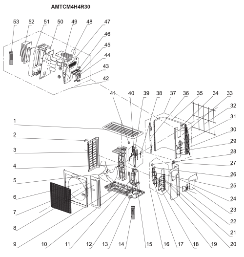
Exploded View and Parts List
| Number | Part Name |
|---|---|
| 1 | Coping |
| 2 | Left Handle |
| 3 | Left Side Plate |
| 4 | Fan Motor |
| 5 | Axial Flow Fan |
| 6 | Cabinet |
| 7 | Front Grill |
| 8 | Front Side Plate |
| 9 | Electrical Heater |
| 10 | Chassis Sub-Assy |
| 11 | Compressor |
| 12 | Electric Heater (Compressor) |
| 13 | Compressor Gasket |
| 14 | Sensor Sub-Assy |
| 15 | Compressor Overload Protector (External) |
| 16 | Valve Support Assy |
| 17 | Strainer A |
| 18 | Electronic Expansion Valve |
| 19 | Electric Expand Valve Fitting |
| 20 | Cut Off Valve |
| 21 | Cut Off Valve |
| 22 | Wiring Cover Sub-Assy |
| 23 | Handle Assy |
| 24 | Right Side Plate |
| 25 | Electric Expand Valve Fitting |
| 26 | Electric Expand Valve Fitting |
| 27 | Wiring Clamp |
| 28 | Electric Expand Valve Fitting |
| 29 | Bidirection Strainer |
| 30 | Gas-Liquid Separator Assy |
| 31 | Reactor |
| 32 | Rear Grill |
| 33 | Clapboard |
| 34 | Cable Cross Loop |
| 35 | Condenser Assy |
| 36 | Condenser Support Plate |
| 37 | Condenser Assy |
| 38 | Pressure Protect Switch |
| 39 | 4-Way Valve |
| 40 | 4-Way Valve Assy |
| 41 | Magnet Coil |
| 42 | Electric Box Assy |
| 43 | Wire Clamp |
| 44 | Terminal board |
| 45 | Wire Clamp |
| 46 | Insulation Gasket |
| 47 | Terminal Board |
| 48 | Magnetic Ring |
| 49 | Cable Cross Loop |
| 50 | Main Board |
| 51 | Electric Box |
| 52 | Radiator |
| 53 | Sensor Sub-Assy |
Piping Sizes
| Liquid Side | Gas Side | Wall Mount Evaporators (A16) | Wall Mount Evaporators (AMT) |
|---|---|---|---|
| 1/4" | 3/8" | A16EW4H4R09 A16EW4H4R12 |
AMTEM4H4R09 AMTEM4H4R12 |
| 1/4" | 1/2" | A16EW4H4R18 | AMTEM4H4R18 |
| 3/8" | 5/8" | A16EW4H4R24 | - |


