ASKEL4H4R36
From Technical Support Wiki
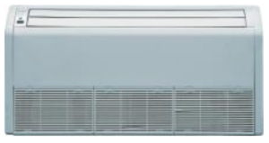
ASKEL4H4R36 is the 16 SEER 36,000 Btu Floor & Ceiling indoor unit of the Sky Split Series.
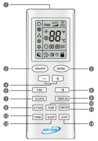
Remote Control
| # | Name | Description |
| 1 | Signal Transmitter | Signal Transmitter |
| 2 | ON/OFF Button | Press this button and the unit will be turned on; press it once more and the unit will be turned off. When turning off the unit, the Sleep function will be canceled, but the presetting time is still remained. |
| 3 | MODE Button | By pressing this button, Auto, Cool, Dry, Fan, Heat mode can be selected circularly. Auto mode is default after power on. Under the Auto mode, the setting temperature will not be displayed; Under the Heat mode, the initial value is 28°C (82°F); under other modes, the initial value is 25°C (77°F). |
| 4 | + (Raise) Button | Preset temperature can be increased by pressing this button. Pressing and holding this button for more than 2 seconds can make the temperature changed quickly until release this button and then transmit this order. The temperature adjustment is unavailable under the Auto mode, but the order can be sent by pressing this button. Centigrade setting range: 16~30; Fahrenheit scale setting range 61~86. |
| 4 | - (Lower) Button | Preset temperature can be decreased by pressing this button. Pressing and holding this button for more than 2 seconds can make the temperature changed quickly until release this button and then transmit this order. The temperature adjustment is unavailable under the Auto mode, but the order can be sent by pressing this button. Centigrade setting range: 16~30; Fahrenheit scale setting range 61~86. |
| 5 | FAN Button | By pressing this button, Auto, Low, Middle, High speed can be circularly selected. After power on, Auto fan speed is default. |
| 6 | SWING UP/DOWN Button | Press this button to set up the swing angle. |
| 7 | CLOCK Button | By pressing this button, the clock is allowed to be set, with the clock symbol blinking, and then press the +/- button to adjust the clock within 5 seconds. If the +/-button is pressed down constantly for more than 2 seconds, the clock setting will be increased or decreased 10 minutes every 0.5 seconds. After that, another press on the CLOCK button accepts the setting. 12:00 is the default, when the wireless remote controller is energized. |
| 8 | TIMER ON Button | When TIMER ON is activated, ON will blink while the clock symbol will disappear. Within 5 seconds it is allowed to set the ON time by pressing the +/- button. Each press will make the time increase or decrease one minute. Besides, the time can also be set by pressing the +/- button constantly. That is, in the early 2.5 seconds, the time will increase/decrease quickly per single minute, and in the late 2.5, the time will increase/decrease per ten minutes. After the desired time value is set, press TIENE ON again to conform the setting within five seconds. After that, another press on TIMER ON will cancel the setting. Prior to this setting, the clock shall be set to the actual time. |
| 9 | X-FAN Button | Pressing this button can activate or deactivate the X-FAN function. In Cool or Dry mode, by pressing this button, if the fan symbol is displayed, it indicates the X-FAN function is activated. By repressing this button, if the fan symbol disappears, it indicates the X-FAN function is deactivated. After energizing, X-FAN OFF is defaulted. If the unit is turned off, X-FAN can be deactivated but can't be activated. |
| 10 | TEMP Button | By pressing this button you can display the indoor setting temperature or the indoor ambient temperature. |
| 11 | TIMER OFF Button | This turns the TIMER function off. |
| 12 | TURBO Button | In Cool or Heat mode, pressing this button can activate or deactivate the TURBO function. When the TURBO function is activated, its symbol (a whirling fan) will be displayed; when the running mode or the fan speed is changed, this function will be canceled automatically. |
| 13 | SLEEP Button | By pressing this button, Sleep On and Sleep Off can be selected. When Sleep is set to On, the crescent moon symbol will display. Under the Fan and Auto modes, this function is not available. |
| 14 | LIGHT Button | Pressing this button will illuminate the buttons on the remote control, enabling usage during darkness. The lightbulb symbol will appear on the the remote's display. |
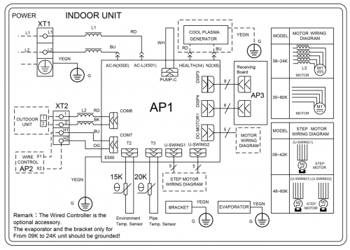
Wiring Diagram
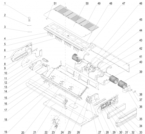
Exploded View and Parts List
| Number | Part Name |
|---|---|
| 1 | Remote Controller |
| 2 | Temperature Sensor |
| 3 | Room Sensor |
| 4 | Swing Lever |
| 5 | Air Louver |
| 6 | Swing Lever |
| 7 | Right Cover Plate |
| 8 | Installation Supporting Frame |
| 9 | Connection Board |
| 10 | Right Side Plate Sub-Assy |
| 11 | Right Foam Assy |
| 12 | Axile Bush |
| 13 | Plate Board of Water Releasing Flume |
| 14 | Water Releasing Flume |
| 15 | Connected Board (Evaporator) |
| 16 | Guide Louver |
| 17 | Rotating Shaft |
| 18 | Front Connection Board Foam Assy |
| 19 | Front Connection Board |
| 20 | Supporter |
| 21 | Rear Side Plate Assy |
| 22 | Fixed Mount |
| 23 | Display Board |
| 24 | Evaporator Assy |
| 25 | Rotating Shaft |
| 26 | Connecting Rod |
| 27 | Rotating Shaft |
| 28 | Stepping Motor |
| 29 | Left Foam Assy |
| 30 | Installation Supporting Frame |
| 31 | Electric Box Assy |
| 32 | Main Board |
| 33 | Terminal Board |
| 34 | Terminal Board |
| 35 | Left Cover Plate |
| 36 | Bracket 1 |
| 37 | O-Gasket of Bearing |
| 38 | Support of Motor Bearing |
| 39 | Cetrifugal Fan |
| 40 | Clapboard Sub-Assy |
| 41 | Rear Connection Board |
| 42 | Front Volute Casing |
| 43 | Rotary Axis Sub-Assy |
| 44 | Joint Slack |
| 45 | Motor Support Sub-Assy |
| 46 | Brushless DC Motor |
| 47 | Rear Volute Casing |
| 48 | Water Tray Assy |
| 49 | Front Grill |
| 50 | Top Cover Board Sub-Assy |
| 51 | Drainage Pipe Sub-Assy |


